Aug 21, 2019 · This article presents a generalized approach toward the dc-link voltage switching ripple analysis in the two-level multiphase pulsewidth modulation (PWM) voltage source
Feb 18, 2016 · In this paper, with the three level voltage inverter using space vector pulse width modulation (SVPWM) as the study object, the ripple current of the inductor current in is analyzed.
Aug 15, 2023 · In this work, recently introduced 9-level T-Type switched-capacitor multilevel inverters are explored for 11-level operation, increasing their reliability in high-temperature
Dec 27, 2023 · Electrolytic capacitor is well known for its high capacitance density, thus most of three-phase inverters employ electrolytic capacitor across their DC-link to suppress the
Jan 1, 2018 · DC-link current is an important parameter for selection and design of DC-link capacitor or battery. Considering the AC current ripple, this study
Jan 4, 2019 · The analysis of the dc-link current and voltage ripple in single-phase H-bridge inverters have been presented in [5, 6]. In case of asymmetric single-phase multi-level
May 16, 2023 · In this paper, we will discuss how to go about choosing a capacitor technology (film or electrolytic) and several of the capacitor parameters, such as nominal capacitance,
Oct 15, 2020 · An analytical approach to size DC link capacitor for an automotive inverter is presented in this paper considering the DC-link ripple voltage and capacitor ripple current. The
Jun 20, 2019 · The voltage ripple is the predominant dc-link capacitor design parameter in automotive traction voltage source inverters. Therefore, the reduction of the voltage ripple
Oct 10, 2023 · In this paper, the DC-link voltage ripple is analyzed for an inverter without electrolytic capacitor. As the capacitance density of non-electrolytic
Jun 18, 2025 · Another stress on the DC capacitor is the voltage rip-ple, caused by the ripple current flowing through it [12, 13]. The capacitor voltage ripple is more dependent on the low
May 13, 2016 · The importance of dielectric materials, ESR, ripple current and other parameters when selecting DC link capacitors for maximum performance in DC link circuits.
May 26, 2017 · Another stress on the DC capacitor is the voltage ripple, caused by the ripple current flowing through it [12, 13]. The capacitor voltage ripple is more dependent on the low
Oct 23, 2018 · In this paper, the DC-link voltage ripple is analyzed for an inverter without electrolytic capacitor. As the capacitance density of non-electrolytic capacitors
Mar 23, 2022 · The LF voltage ripple is a function of the inductor ripple current going through the output capacitor''s impedance. This impedance is formed by the capacitance value along with
Dec 23, 2024 · These include capacitance, voltage rating, and the ripple current it can handle. These factors determine how well the capacitor performs under specific operational conditions.
Aug 15, 2023 · And because of the large number of switches, the engineers are reluctant to go for more than 5-level inverters due to significant semiconductor waste issues. So, to target low
Dec 27, 2023 · As the capacitance density of non-electrolytic capacitors are significantly lower than electrolytic capacitors, for a non- electrolytic capacitor based three-phase inverter, the DC
Aug 26, 2021 · Abstract— Aluminum electrolytic capacitors are widely used in all types of inverter power systems, from variable-speed drives to welders to UPS units. This paper discusses the
Oct 1, 2018 · In this paper, the DC-link voltage ripple is analyzed for an inverter without electrolytic capacitor. As the capacitance density of non-electrolytic
Dec 22, 2020 · Increased capacitance can therefore be required for decreasing the dc-link capacitor voltage ripple caused by the inverter front end (e.g. a recti er) or for other purposes,
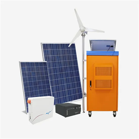
Aug 9, 2024 · Photovoltaic systems are generating interest as efficient renewable energy sources owing to the lowering of the price and cost of power generation with the progress of research
Nov 7, 2024 · The DC-link capacitor represents a critical component in electric vehicle traction inverters, given that it constitutes the largest single volume within a traction inverter. The DC
May 18, 2019 · The voltage ripple amplitudes of the two dc-link capacitors are theoretically estimated as a function of both amplitude and phase angle of output current and the inverter
It should be noted that at the power factor of 0.4, the voltage ripple is approximately the maximum voltage ripple which is 8. Based on the simulation results, the power loss of DC- link capacitor is estimated and compared with the power loss of the electrolytic capacitor based inverter. The result is shown in Table III.
This suggests that a similar approach may be applied to the analysis of the inverter input current, which draws a sequence of pulses from the DC link capacitor. Both of these sets of pulses will cause voltage ripple as well as ripple current and its attendant heating.
KO6î (14) As a low switching frequency electrolytic capacitor based inverter has the same RMS of DC-link current ripple as a high switching frequency film capacitor based inverter, the power loss of DC-link is only dependent upon the capacitor ESR according to (12).
The voltage ripple amplitudes of the two dc-link capacitors are theoretically estimated as a function of both amplitude and phase angle of output current and the inverter modulation index. In particular, peak-to-peak distribution and maximum amplitudes of the capacitor voltage switching ripple over the fundamental period are obtained.
This paper presents the voltage ripple analysis of the voltage source inverter under the modulation methods of SPWM and SVPWM. The results show that the DC-link voltage ripple has special patterns which relate to switching frequency, modulation ratio, output current amplitude, load power factor, and reference voltage angle.
Since capacitor lifetime and failure rate are exponential functions of temperature and thus of ripple current, the ripple current stress on the DC link capacitor is critical and needs to be managed carefully and conservatively.
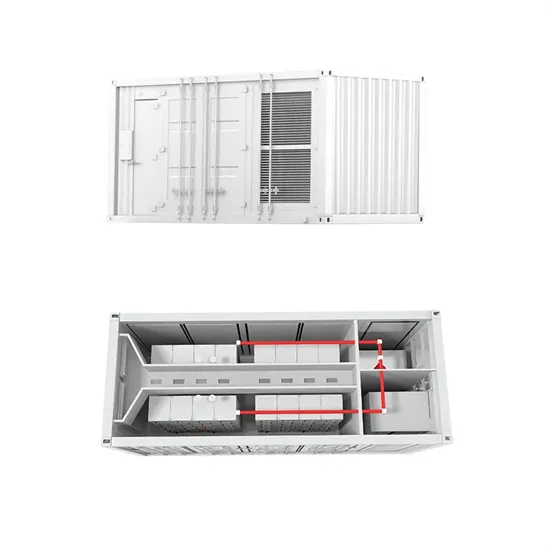
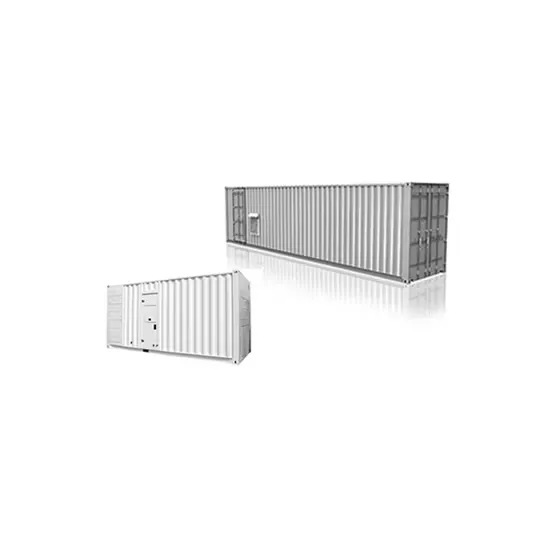
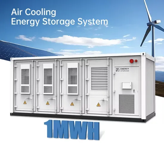
The global solar storage container market is experiencing explosive growth, with demand increasing by over 200% in the past two years. Pre-fabricated containerized solutions now account for approximately 35% of all new utility-scale storage deployments worldwide. North America leads with 40% market share, driven by streamlined permitting processes and tax incentives that reduce total project costs by 15-25%. Europe follows closely with 32% market share, where standardized container designs have cut installation timelines by 60% compared to traditional built-in-place systems. Asia-Pacific represents the fastest-growing region at 45% CAGR, with China's manufacturing scale reducing container prices by 18% annually. Emerging markets in Africa and Latin America are adopting mobile container solutions for rapid electrification, with typical payback periods of 3-5 years. Major projects now deploy clusters of 20+ containers creating storage farms with 100+MWh capacity at costs below $280/kWh.
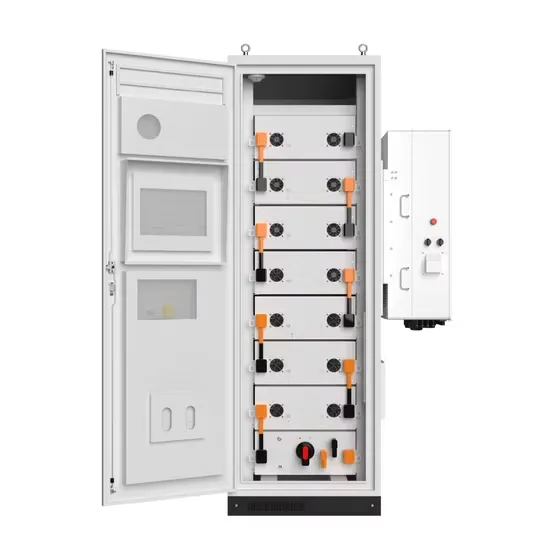
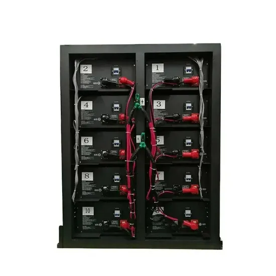
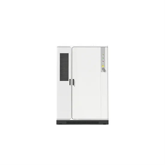
Technological advancements are dramatically improving solar storage container performance while reducing costs. Next-generation thermal management systems maintain optimal operating temperatures with 40% less energy consumption, extending battery lifespan to 15+ years. Standardized plug-and-play designs have reduced installation costs from $80/kWh to $45/kWh since 2023. Smart integration features now allow multiple containers to operate as coordinated virtual power plants, increasing revenue potential by 25% through peak shaving and grid services. Safety innovations including multi-stage fire suppression and gas detection systems have reduced insurance premiums by 30% for container-based projects. New modular designs enable capacity expansion through simple container additions at just $210/kWh for incremental capacity. These innovations have improved ROI significantly, with commercial projects typically achieving payback in 4-7 years depending on local electricity rates and incentive programs. Recent pricing trends show 20ft containers (1-2MWh) starting at $350,000 and 40ft containers (3-6MWh) from $650,000, with volume discounts available for large orders.