New energy vehicle DC 320V~450V to AC 220V discharge charging pure sine wave inverter rear stage board 4000W 5000W 8000W 4.6 18 Reviews ౹ 67 sold US $40.32 15% off US $47.44
Eg6462|Upgrade your power conversion with the 1000W inverter rear stage drive board, featuring advanced EG8011+EG2126 chips for pure sine wave output and customizable settings for
When the drive signal runs to time t2, the gate of Q1 becomes high level, Q1 starts to conduct, the potential of the midpoint of the half bridge rises sharply, C2 is charged by the bus voltage, and
Mar 20, 2025 · EV Engineering News A closer look at multilevel traction inverters Posted March 20, 2025 by Jeffrey Jenkins & filed under Features, Newswire,
Apr 3, 2022 · Re: Small drive unit inverter teardown and repair by js1tr3 » Sun Apr 03, 2022 11:40 pm Yup, checked that is a It''s a breather gasket. Not sure how u can hit all of them at once
2.1 Power Part: As in the power part of Fig. 1, the SCI booster (front stage) and DC-link inverter (rear stage) are connected in cascade between VS and Vo . The main function of the front
Jul 19, 2022 · Buy New Upgraded Version 1000W Inverter Rear Stage Drive Board EGS003 EG8011+EG2126 Drive Module for 7.12 usd in the online store Jin rong electronics co., LTD.
Oct 28, 2024 · Abstract This paper focuses on the integration technology of electric vehicle motor driving system and on-board charging system. The front-stage bi-directional AC/DC converter
The driving signals of the bridge arm switch transistors Q 1 and Q 2 on the primary-side of the rear-stage converter and the input voltage waveform of the A-phase circuit are shown in Fig. 18.
Sep 16, 2009 · Design a static CMOS inverter with 0.4pF load capacitance. Make sure that you have equal rise and fall times. Layout the inverter using the Mentor tools, extract parasitics,
Sep 9, 2021 · The power stage was developed to support customers during their first steps in designing 48V inverter for Belt-driven Starter Generator (BSG) application. The document
Oct 14, 2016 · Using an AC motor requires an inverter power stage to convert DC voltage from the battery to a variable frequency voltage. This TI Design implements an AC traction motor
Principle of the circuit diagram of the rear stage of the high-frequency inverter. The basic function of the rear stage circuit is to invert the high-voltage DC boosted by the front stage into AC.
Apr 1, 2023 · ABSTRACT This technical white paper explores key system trends, architecture, and technology for traction inverters. The devices and technologies used to enable traction
This product is a high-power sine wave inverter board, which can be used for solar inverter conversion, modified wave inverter to sine wave inverter, high frequency square wave inverter
Apr 1, 2023 · The three legs of the inverter convert the DC battery voltage into three phases of AC voltage and current to drive the motor. Two current measurements and a position
Aug 29, 2005 · Figure 2 shows an example of a phase-to-phase short-circuit. A desaturation detection circuit is embedded in both the high- and low-side output stages for each of the three
Dec 30, 2024 · The 5000W board adopts a dedicated IGBT driver board using 8pcs high-power TO-274 IGBT. - Circuit board of 5000W full load version: 206 x 96 x 70mm/8.1 x 3.8 x 2.8". It is
Dec 22, 2023 · The power stage implementations of inverter designs need robust logic buffers and gate logic to implement control logic for coordinating the gate drive functionality.
Apr 1, 2025 · In light of the experiences gained from previous micro grid-connected inverters, a dual Buck micro grid-connected inverter based on a small signal model is proposed. The front
Dec 22, 2023 · Criteria such as drive strength, channel count, voltage range, temperature range, and package size can all play a critical role in a design. Table 1 provides a guide for selecting
Feb 4, 2025 · An important piece of information about an inverter stage is its static transfer characteristic, vOUT(vIN). To calculate this characteristic we sum the currents into the output
48-VDCBattery Powered Inverter Power Stage Reference Design for 5-kW Forklift AC Traction Motor The share of ACIM drives over their DC counterparts for forklift traction is steadily increasing. Using an AC motor requires an inverter power stage to convert DC voltage from the battery to a variable frequency voltage.
The inverter stage is a basic building block for digital logic circuits and memory cells. A generic inverter stage is illustrated below on the left. It consists of two devices,
The inverter specification describes the working condition of the power stage as shown in Table 2. This specification is not directly limited by the power stage. The power stage is designed for such inverter and motor system. The target motor is Permanent Magnet Synchronous Motor (PMSM).
48-VDCBattery Powered Inverter Power Stage Reference Design for 5-kW Forklift AC Traction Motor The turnon and turnoff times of the MOSFETs are independently controlled. A slow turnon is used to minimize overshoot and ringing on the phase output due to unavoidable circuit layout parasitics.
The typical battery voltages are 24, 36, and 48 VDC, and the traction inverters are rated up to 8 kW. This necessitates using multiple MOSFETs in parallel to achieve the required current and power rating.
48-VDCBattery Powered Inverter Power Stage Reference Design for 5-kW Forklift AC Traction Motor All trademarks are the property of their respective owners. Description This TI Design provides a reference solution for a three-phase MOSFET-based inverter to drive an AC induction motor for traction in forklifts.
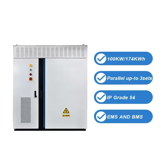
The global solar storage container market is experiencing explosive growth, with demand increasing by over 200% in the past two years. Pre-fabricated containerized solutions now account for approximately 35% of all new utility-scale storage deployments worldwide. North America leads with 40% market share, driven by streamlined permitting processes and tax incentives that reduce total project costs by 15-25%. Europe follows closely with 32% market share, where standardized container designs have cut installation timelines by 60% compared to traditional built-in-place systems. Asia-Pacific represents the fastest-growing region at 45% CAGR, with China's manufacturing scale reducing container prices by 18% annually. Emerging markets in Africa and Latin America are adopting mobile container solutions for rapid electrification, with typical payback periods of 3-5 years. Major projects now deploy clusters of 20+ containers creating storage farms with 100+MWh capacity at costs below $280/kWh.
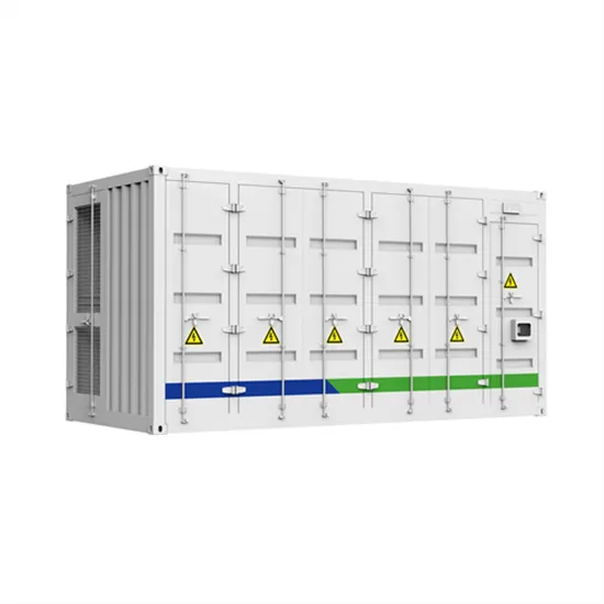
Technological advancements are dramatically improving solar storage container performance while reducing costs. Next-generation thermal management systems maintain optimal operating temperatures with 40% less energy consumption, extending battery lifespan to 15+ years. Standardized plug-and-play designs have reduced installation costs from $80/kWh to $45/kWh since 2023. Smart integration features now allow multiple containers to operate as coordinated virtual power plants, increasing revenue potential by 25% through peak shaving and grid services. Safety innovations including multi-stage fire suppression and gas detection systems have reduced insurance premiums by 30% for container-based projects. New modular designs enable capacity expansion through simple container additions at just $210/kWh for incremental capacity. These innovations have improved ROI significantly, with commercial projects typically achieving payback in 4-7 years depending on local electricity rates and incentive programs. Recent pricing trends show 20ft containers (1-2MWh) starting at $350,000 and 40ft containers (3-6MWh) from $650,000, with volume discounts available for large orders.