Oct 26, 2022 · H-bridge inverter is a common topology used for single-phase applications. Due to its limited voltage gain, a two-stage power conversion with a front-end dc–dc converter is
Sep 24, 2024 · This article proposed an integrated inverter to achieve voltage boosting and leakage current suppression. The proposed inverter is obtained by only adding two d
Jan 1, 2023 · Abstract A current-source single-stage multi-input high-frequency-link grid-connected inverter and a three-mode one-cycle control strategy are proposed and deeply
Dec 26, 2024 · Local Voltage Control: In islanding mode, the inverter adjusts the voltage based on local load demands, ensuring stable voltage at the load end.
Feb 14, 2025 · In view of the different control objectives and stable operation adjustment of two-stage photovoltaic inverters in on-grid mode and off-grid mode, this paper proposes a
Sep 24, 2024 · This article proposed an integrated inverter to achieve voltage boosting and leakage current suppression. The proposed inverter is obtained by only adding two diodes to
Jan 1, 2022 · When the input voltage is low, the traditional voltage source inverter is usually added a DC-DC boost circuit at its front stage. So, the step-up inverter can be realized by
Dec 1, 2016 · In this paper, the characteristics, design and control parameters of a 200 W micro-inverter, consisting of two conversion stages are presented; the first one is implemented by a
Apr 1, 2023 · This solution implements an isolated DC-DC stage with the MPPT algorithm, to make use of the full capacity of the solar panel. The solar inverter maintains its input voltage at
The dimming signal and feedback signal control the front-stage voltage-adjustment unit to adjust the voltage of the input power beforehand to vary the output of the inverter; therefore, the half
Mar 30, 2025 · This paper presents a controller for a direct current (DC) grid-connected single-stage solar photovoltaic (PV) converter. The proposed controller provides both static and
Understanding front stage voltage (typically 12V-48V for most systems) helps optimize power conversion efficiency. Whether you''re designing solar arrays or industrial UPS systems, proper
Aug 11, 2025 · Based on the power relationship between DC-link capacitors and FC, the proposed technique adjusts the duty cycles of redundant 1-level switching states to balance the DC
Jul 18, 2025 · Analyze and optimize the efficiency of single-stage solar inverters for seamless DC-AC conversion. Explore power loss reduction, modulation strategies, and grid compliance
Jul 4, 2023 · A. Bulk Charging During the initial phase of battery charging, the inverter charger operates in the bulk charging mode. It supplies a high current
May 11, 2022 · To control the inverter stage for desired operation, voltage and current need to be sensed for processing by the digital controller. The design implements sensing scheme based
Feb 4, 2025 · An important piece of information about an inverter stage is its static transfer characteristic, vOUT(vIN). To calculate this characteristic we sum the currents into the output
Sep 13, 2022 · A current-source single-stage multi-input high-frequency-link grid-connected inverter and a three-mode one-cycle control strategy are proposed and deeply investigated in
Why Front Stage Voltage Matters The front stage, often called the DC-DC converter stage, typically operates at 12V to 48V in most residential and commercial systems. However,
Mar 4, 2025 · This paper designed a modulation strategy that adjusts k in relation to PV voltage to minimize Qre, ensuring optimized power conversion under varying conditions. In DAB micro
May 31, 2018 · Abstract : The buck-boost inverter provides boosting and inversion function in a single power processing stage based on the front end buck-boost converter characteristics.
Jul 2, 2009 · A front-stage voltage-adjustment inverter, which receives an input power and converts said input power into a driving power to drive at least one load, and which comprises:
Enter 60 Hz for frequency for the AC waveform. This will be the frequency of the inverter output. Under Inverter Power Stage Parameters, enter 110 VRMS for the output voltage. This will be the value that the AC output will regulate to. Type Ctrl+S to save the page. Right-click on the project name. Select Rebuild Project.
The inverter stage is a basic building block for digital logic circuits and memory cells. A generic inverter stage is illustrated below on the left. It consists of two devices,
The inverter starts as soon as the DC bus voltage is present at a greater level than 10% of the AC maximum. Observe the controlled AC voltage waveform on the output. The frequency and the amplitude of the AC voltage is determined by the values on the powerSUITE page of the solution. If any changes are required, stop the inverter.
Finally, a 300 W prototype is built for experimental verification. This article proposed an integrated inverter to achieve voltage boosting and leakage current suppression. The proposed inverter is obtained by only adding two diodes to the existing bimodal inverter.
Voltage source inverters (VSIs) are commonly used in uninterruptible power supplies (UPS) to generate a regulated AC voltage at the output. Control design of such inverter is challenging because of the unknown nature of load that can be connected to the output of the inverter.
For the voltage source inverter, TI recommends to keep the crossover of the inner current loop at greater than ten times the AC frequency, which is met by this compensator, and no changes are needed in the design. If an adapted solution is not met, the compensator must be changed to ensure the crossover of the current loop meets this requirement.
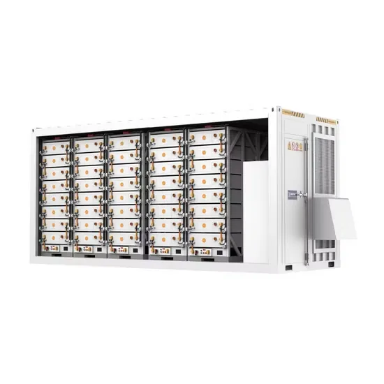
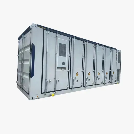
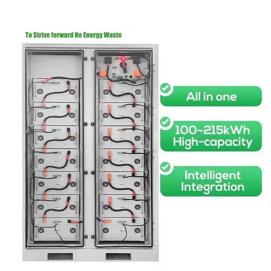
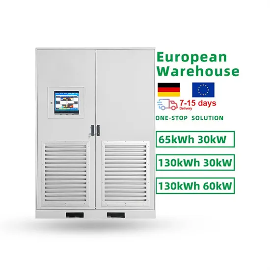
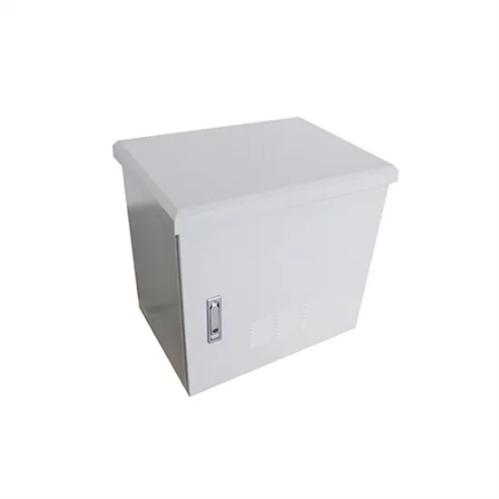
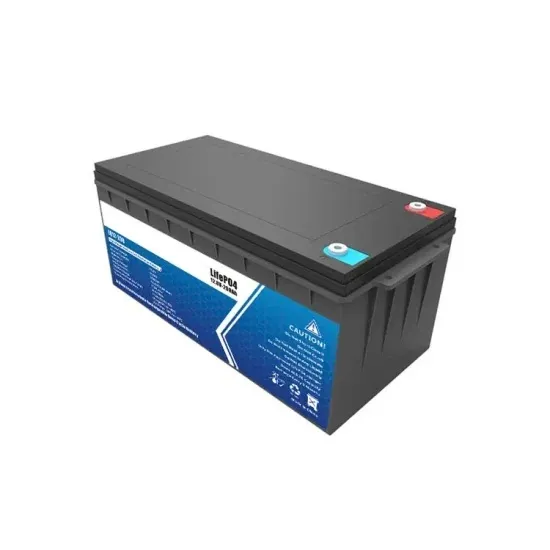
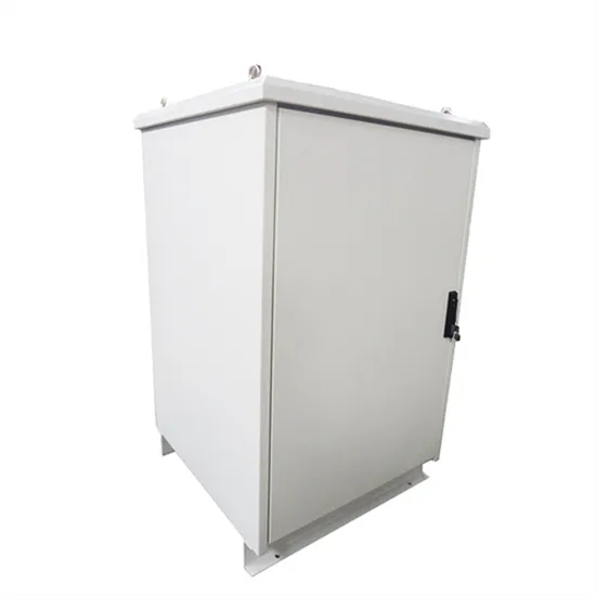
The global solar storage container market is experiencing explosive growth, with demand increasing by over 200% in the past two years. Pre-fabricated containerized solutions now account for approximately 35% of all new utility-scale storage deployments worldwide. North America leads with 40% market share, driven by streamlined permitting processes and tax incentives that reduce total project costs by 15-25%. Europe follows closely with 32% market share, where standardized container designs have cut installation timelines by 60% compared to traditional built-in-place systems. Asia-Pacific represents the fastest-growing region at 45% CAGR, with China's manufacturing scale reducing container prices by 18% annually. Emerging markets in Africa and Latin America are adopting mobile container solutions for rapid electrification, with typical payback periods of 3-5 years. Major projects now deploy clusters of 20+ containers creating storage farms with 100+MWh capacity at costs below $280/kWh.
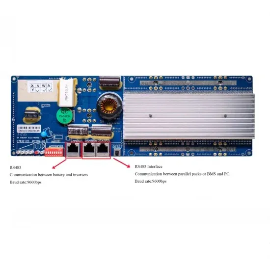
Technological advancements are dramatically improving solar storage container performance while reducing costs. Next-generation thermal management systems maintain optimal operating temperatures with 40% less energy consumption, extending battery lifespan to 15+ years. Standardized plug-and-play designs have reduced installation costs from $80/kWh to $45/kWh since 2023. Smart integration features now allow multiple containers to operate as coordinated virtual power plants, increasing revenue potential by 25% through peak shaving and grid services. Safety innovations including multi-stage fire suppression and gas detection systems have reduced insurance premiums by 30% for container-based projects. New modular designs enable capacity expansion through simple container additions at just $210/kWh for incremental capacity. These innovations have improved ROI significantly, with commercial projects typically achieving payback in 4-7 years depending on local electricity rates and incentive programs. Recent pricing trends show 20ft containers (1-2MWh) starting at $350,000 and 40ft containers (3-6MWh) from $650,000, with volume discounts available for large orders.