ABSTRACT Most of the renewable energy systems require an inverter that converts direct current (DC) to alternating current (AC) as a power supply. A lot of efforts has been made to achieve
High-frequency pulse AC link inverter, as shown in Figure 1. The circuit structure consists of a high-frequency inverter ( push -pull, half- bridge, full- bridge), a high-frequency transformer,
Oct 27, 2024 · Fig. 2 Waveform of Unipolar PWM Single Phase Inverter During positive half-cycle, when V sine is greater than V tri then V a is V dc /2 and when V sine is less than V tri then V a
A multilevel inverter has several advantages over a conventional two-level inverter that uses high switching frequency pulse width Modulation (PWM). The most attractive features of a
4 days ago · Addressing waveform quality concerns in high-frequency inverters demands a multi-faceted approach. Advanced filtering techniques, implemented through LC or resonant circuits,
Dec 23, 2020 · In this paper, a class of new HFAC inverter topologies are proposed for use of single-phase, three-phase, multi-phase, and multi-levels. A coupled inductor bridge arm is
Aug 5, 2024 · The switching loss of the traditional DPWM method is large. Therefore, this paper improves the traditional DPWM method by adding a clamping interval to reduce the switching
Oct 1, 2018 · The requirements for the grid-connected inverter include; low total harmonic distortion of the currents injected into the grid, maximum power point tracking, high efficiency,
Oct 1, 2022 · zero voltage switching needed for high efficiency operation at high frequency. While an inverter can be inductively preloaded to provide the needed inductive load current for zero
Jan 31, 2024 · An inverter controller can be implemented by considering the block diagram shown in Figure 2. Figure 2: Inverter Schematic A high frequency triangular waveform, generally in
Mar 20, 2013 · The digital implementations of Sinusoidal Pulse Width Modulation (SPWM) generators have dominated over their counterparts based on analog circuits. In this paper, an
Apr 1, 2021 · Such drive systems are usually fed by semiconductor switch-based inverters, which, unlike balanced pure sine-wave AC sources, produce large-amplitude, high-frequency
The switching dead time to protect the inverter main transistors from the arm shortage is investigated. The dead time causes not only waveform distortion, but also zero clamping
Dec 20, 2023 · This article will give you a detailed introduction and comparison of inverter waveform, including the principles of generating different waveforms,
Feb 15, 2025 · In the proposed topology, the DC-link capacitors and high-frequency transformer have been eliminated to deliver output power to the load in a trapezoidal waveform instead of
Sep 1, 2020 · A low-pass inductor-capacitor (LC) or inductor-capacitor-inductor (LCL) type filter is used for mitigating the high-frequency harmonics from the bridge output Vdvmi−spwm[9]while
In this paper, Simulation & Hardware development of High frequency Inverter with 90KHz frequency with Pulse Width Modulation switching strategy is presented. The inverter topology
Nov 27, 2024 · A high frequency triangular waveform, generally in several kHz, is necessary to generate the SPWM signals. This task is implemented with finite state machines
Mar 28, 2020 · This was powering 1300W load with a high-frequency inverter that has pretty good set of electrolytic capacitors. Would expect similar current for a 48V battery inverter powering
Oct 29, 2015 · In many applications it is important for an inverter to be of relatively small size and lightweight. This can be achieved by using a high-frequency (HF) link inverter topology. A
Abstract: A new topology of the high frequency alternating current (HFAC) inverter bridge arm is proposed which comprises a coupled inductor, a switching device and an active clamp circuit. Based on it, new single-phase and three- phase inverters are proposed and their operating states are analysed along with the traditional H-bridge inverter.
However, unlike ‘traditional’ grid-connected machines, such inverters inherently produce high-frequency, large-amplitude common-mode voltage waveforms, unless specific design measures are taken.
The traditional H-bridge inverter arm can generate outputs of 0 and ±Vin between the central node, as in Fig. 2a. It can be modi ed by fi replacing the upper switches with coupled inductors, as shown in Fig. 2b.
ut Pmax VINmax13:56MHz21:31kW375VIV. CONTROL SCHEMEA. Control ChallengesIn Section II the high frequency variable load inverter was modeled with each constituent inverter as an ideal voltage source that could drive any resistiv / inductive load, only sub-ject to maximum output voltage and current limits. However, real inverters h
In many applications it is important for an inverter to be of relatively small size and lightweight. This can be achieved by using a high-frequency (HF) link inverter topology. A popular HF link inverter topology is the so-called DC/DC converter type, Fig. 2 a
In an alternative version, the HF bridge inverter produces an HF PWM wave, thus reducing the transformer losses [4, 5]. In the last two design methods the power flow is uni- directional from the DC input source to the AC output load because of the diode rectifier. However, in applica- tions involving renewable energy source systems where
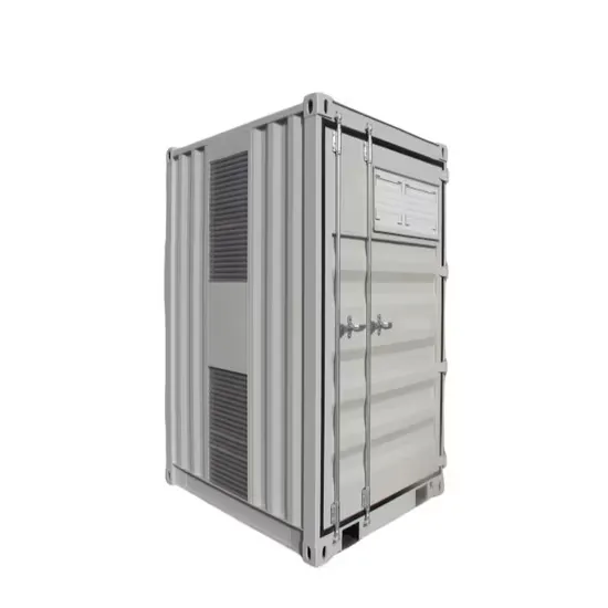
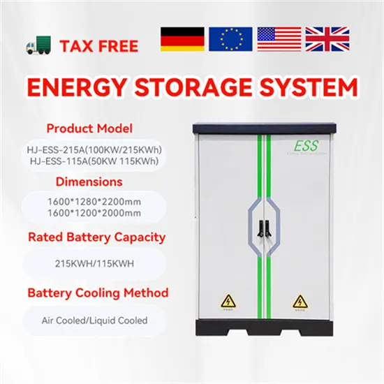
The global solar storage container market is experiencing explosive growth, with demand increasing by over 200% in the past two years. Pre-fabricated containerized solutions now account for approximately 35% of all new utility-scale storage deployments worldwide. North America leads with 40% market share, driven by streamlined permitting processes and tax incentives that reduce total project costs by 15-25%. Europe follows closely with 32% market share, where standardized container designs have cut installation timelines by 60% compared to traditional built-in-place systems. Asia-Pacific represents the fastest-growing region at 45% CAGR, with China's manufacturing scale reducing container prices by 18% annually. Emerging markets in Africa and Latin America are adopting mobile container solutions for rapid electrification, with typical payback periods of 3-5 years. Major projects now deploy clusters of 20+ containers creating storage farms with 100+MWh capacity at costs below $280/kWh.
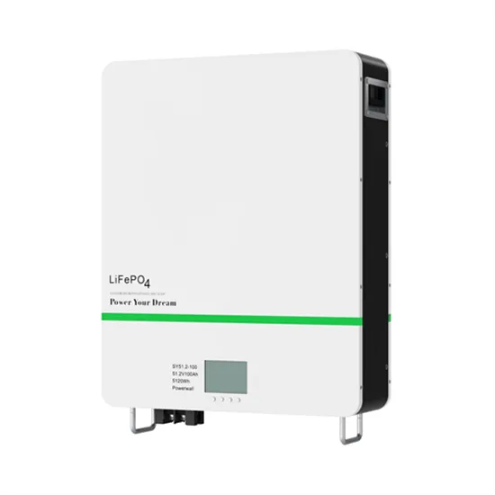
Technological advancements are dramatically improving solar storage container performance while reducing costs. Next-generation thermal management systems maintain optimal operating temperatures with 40% less energy consumption, extending battery lifespan to 15+ years. Standardized plug-and-play designs have reduced installation costs from $80/kWh to $45/kWh since 2023. Smart integration features now allow multiple containers to operate as coordinated virtual power plants, increasing revenue potential by 25% through peak shaving and grid services. Safety innovations including multi-stage fire suppression and gas detection systems have reduced insurance premiums by 30% for container-based projects. New modular designs enable capacity expansion through simple container additions at just $210/kWh for incremental capacity. These innovations have improved ROI significantly, with commercial projects typically achieving payback in 4-7 years depending on local electricity rates and incentive programs. Recent pricing trends show 20ft containers (1-2MWh) starting at $350,000 and 40ft containers (3-6MWh) from $650,000, with volume discounts available for large orders.