Mar 1, 2015 · Abstract This paper presents a performance characterization and efficient modeling of the dc-side interactions between renewable dc resources and interfacing voltage-source
Jun 14, 2022 · 1 Introduction This application note describes the design of a three-phase Brushless DC (BLDC) motor drive based on Freescale''s MC56F8257 digital signal controller
Aug 25, 2017 · 2 Key System Specifications Single Phase Inverter (DC-AC) with Inductor Capacitor Output Filter and output voltage control. Table 1 shows the key system
Jan 19, 2024 · In electric vehicle (EV) charging and solar inverter systems, current sensors measure current flow by monitoring the voltage drop across a shunt resistor or the magnetic
Sep 3, 2014 · Many fields use this inverter, such as motor control, UPS, and solar inverter systems. The main function of the inverter is to convert the DC power to AC power by using
Sep 30, 2020 · AC/DC, DC-DC bi-directional converters for energy storage and EV applications Ramkumar S, Jayanth Rangaraju Grid Infrastructure Systems
Jan 21, 2021 · Inverter components such as power semiconductor and DC link capacitors are designed to operate within a safe current range and temperature range. Out-of-range inverter
Mar 5, 2025 · The influence of dc-side dynamics in grid-forming inverters has emerged as a critical area of study due to its implications for stability and control. A key yet unresolved
Feb 3, 2025 · In the absence of a dc-link con-troller (in the grid-connected inverter or with additional stor-age at the dc-link), adjusting the PV power output lower than the maximum
May 11, 2022 · Description This reference design implements single-phase inverter (DC/AC) control using a C2000TM microcontroller (MCU). The design supports two modes of operation
Feb 4, 2025 · The central inverters have five, eight or twelve fused inputs respectively for the DC distributor box. Several devices can be connected together on the AC side. This makes
May 18, 2021 · Conclusion DC Input Disturbance is a common fault of solar PV systems and in more than 90% of cases, faults of this type are caused on the DC side. This can include PV
Mar 7, 2022 · Figure 4 showing a GTO based inverter used to study different type of converter station faults. DC supply is provided by rectifier at transmitting side and then this inverter
Mar 31, 2017 · Description The TIDA-00778 design demonstrates fast and accurate current sensing for a three-phase motor driven with sensorless field-oriented control (FOC). Drives
Mar 19, 2025 · Common solar application scenarios with hall-effect current sensing include string inverter, residential inverter, hybrid inverter, micro inverter, solar power optimizer and smart
Jun 10, 2023 · This letter presents a hardware demonstrator of an all-SiC three-level T-type (3LTT) inverter with the common-mode (CM) EMI filter stages
Jul 20, 2023 · The DC-side dynamics of two-stage grid-forming (GFM) inverters are often neglected or oversimplified in power system studies, although they play a vital role in
1 day ago · The conventional three-level inverter lacks voltage boosting capability and necessitates measures to balance the neutral point voltage. When the DC voltage is low, a
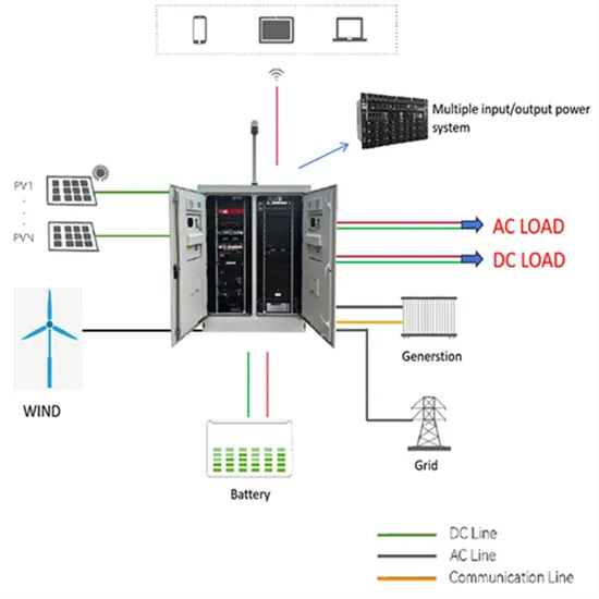
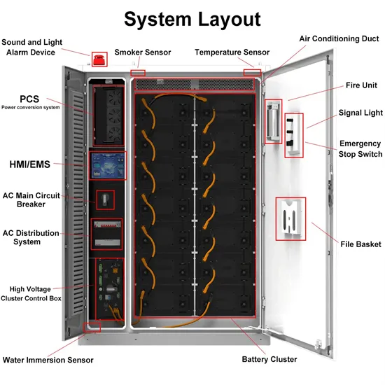
Sep 15, 2023 · The second section is the intermediate compartment that includes the inverters which are used to convert the DC power to AC power. So, the inverter is the main transition
Jan 7, 2024 · By comparing the high-side and low-side sensing schemes, this article will demonstrate the advantages of high-side Hall current sensor, including accurate detection of
Jan 19, 2024 · Bandwidth and speed are necessary for actively controlling switching systems, such as isolated DC/DC converters in solar energy. Design complexity is another crucial factor
Nov 1, 2021 · There are multiple fault causes coupling in DC side of photovoltaic inverter. The changes of voltage, current and power are derived by fault mechanism analysis. The
There are multiple fault causes coupling in DC side of photovoltaic inverter. The changes of voltage, current and power are derived by fault mechanism analysis. The differences of failure feature are used to locate the fault cause.
In electric vehicle (EV) charging and solar inverter systems, current sensors measure current flow by monitoring the voltage drop across a shunt resistor or the magnetic fields generated by current flowing through a conductor. These high-voltage systems use current flow information to control and monitor power conversion, charging and discharging.
Due to the different mechanisms of DC faults caused by different causes, there are obvious differences in characteristic such as voltage and current. Using the fault features of grid-connected inverters, a fault diagnosis process combining multiple technical means is proposed.
A traction inverter controls the electric motor and is a key component in the HEV/EV drivetrain. A traction inverter requires accurate current sensing at high common-mode voltages. Current measurements in traction inverters can therefore be realized using one of two shunt-based methods.
In order to limit output level of inverter, there is often a limiter in control circuit. The inverter output dq axis voltage ud and uq after passing through current inner loop are used as the input of sinusoidal vector pulse width modulation (SVPWM), and then realizes the conversion from DC to AC. Fig. 2.
2.2. DC overvoltage fault The condition of DC overvoltage fault in inverter is that the DC capacitor voltage exceeds maximum allowable voltage Umax and maintains for a period of time, which triggers overvoltage protection and causes the inverter to stop.
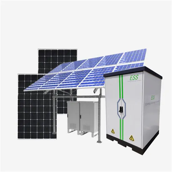
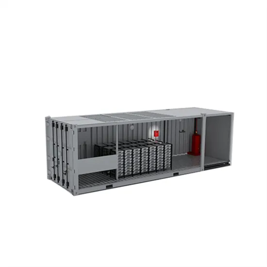
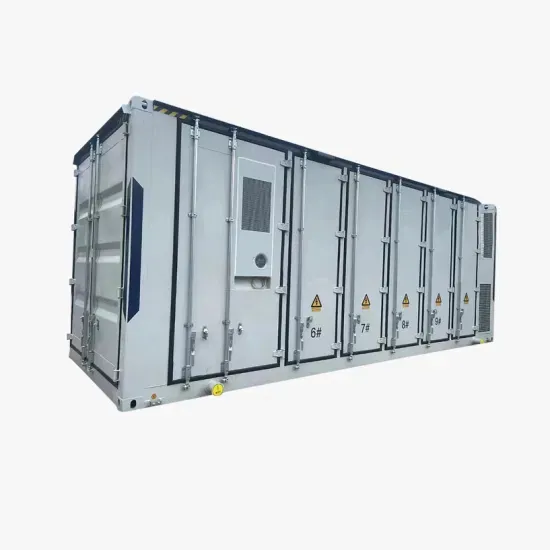
The global solar storage container market is experiencing explosive growth, with demand increasing by over 200% in the past two years. Pre-fabricated containerized solutions now account for approximately 35% of all new utility-scale storage deployments worldwide. North America leads with 40% market share, driven by streamlined permitting processes and tax incentives that reduce total project costs by 15-25%. Europe follows closely with 32% market share, where standardized container designs have cut installation timelines by 60% compared to traditional built-in-place systems. Asia-Pacific represents the fastest-growing region at 45% CAGR, with China's manufacturing scale reducing container prices by 18% annually. Emerging markets in Africa and Latin America are adopting mobile container solutions for rapid electrification, with typical payback periods of 3-5 years. Major projects now deploy clusters of 20+ containers creating storage farms with 100+MWh capacity at costs below $280/kWh.
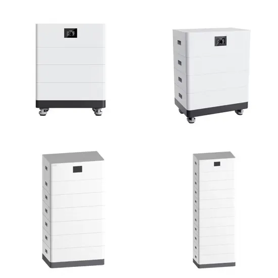
Technological advancements are dramatically improving solar storage container performance while reducing costs. Next-generation thermal management systems maintain optimal operating temperatures with 40% less energy consumption, extending battery lifespan to 15+ years. Standardized plug-and-play designs have reduced installation costs from $80/kWh to $45/kWh since 2023. Smart integration features now allow multiple containers to operate as coordinated virtual power plants, increasing revenue potential by 25% through peak shaving and grid services. Safety innovations including multi-stage fire suppression and gas detection systems have reduced insurance premiums by 30% for container-based projects. New modular designs enable capacity expansion through simple container additions at just $210/kWh for incremental capacity. These innovations have improved ROI significantly, with commercial projects typically achieving payback in 4-7 years depending on local electricity rates and incentive programs. Recent pricing trends show 20ft containers (1-2MWh) starting at $350,000 and 40ft containers (3-6MWh) from $650,000, with volume discounts available for large orders.