When working with 24V inverters, one common question arises: "How many turns does the coil need?" While the answer depends on specific design parameters, this guide will break down
The transformer should have a 24V primary winding and an appropriate secondary winding to achieve the desired output voltage. A transformer with a higher frequency (50kHz to 100kHz)
Feb 22, 2025 · EXAMPLE: For a decent 24V 3000W inverter with 90% efficiency we calculated the fuse size as 175A. Looking in the table on page 3 we see that a 2AWG wire with a 90oC

Understanding the primary voltage turns in an inverter is critical for optimizing energy conversion efficiency. This article explores the factors influencing winding configurations, industry
What is the ratio of turns between the primary coil winding and the secondary coil winding of a transformer designed to triple its input voltage? A—Primary will have one-third as many turns

Use a 24V inverter circuit to convert DC voltage from a battery or power source into stable AC output suitable for household or industrial appliances. This circuit typically involves
Sep 19, 2024 · What is a Step-Down Transformer? A transformer is a device that transfers electrical energy from one circuit to another through electromagnetic induction. It consists of
Jul 29, 2024 · This delay lets the AC line voltage and frequency stabilize before the control logic phase-locks the inverter''s output to the utility input. The control logic then de-energizes the
Aug 6, 2011 · The primary to secondary turns ratio can be es-tablished to efficiently accommodate widely dif-ferent input/output voltage levels. Multiple secondaries with different numbers of
The 24V power inverter circuit diagram outlines the various parts required for the inverter to function. This includes the main transformer, which steps up the DC voltage to AC, and the output transformer, which steps down the voltage level further. Other components such as the rectifier, capacitor, diodes, and driver transistors are also included.
And how does it affect the power delivery process? Essentially, a 24v inverter circuit diagram refers to a type of electrical diagram that shows how a 24-volt power supply can be used to convert power from alternating current (AC) to direct current (DC). This is important because AC and DC are two completely separate forms of electricity.
The voltage setting for a 24v circuit will usually be somewhere between 20 and 28 volts. It is important to select the correct voltage for the particular device or appliance. If the voltage is too low, the device may not operate as expected; if the voltage is too high, the device may be damaged.
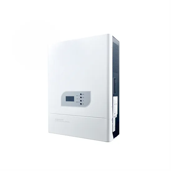
OPERATION Power ON/OFF Once the unit has been properly installed and the batteries are connected well, simply press On/Off switch (located on the right corner of the rear panel) to turn on the unit. Operation and Display Panel The operation and display panel, as shown in the chart below, are on the front panel of the inverter.
For example, a 2.5 to 1 turns ratio may be desirable between a 12 Volt and a 5 Volt output. This is easily accomplished with a 2-turn 5V secondary and a 5-turn 12V winding. But if the 5V secondary has only 1 turn, the only choice for the 12V secondary is 3 turns, which may result in excessive linear post-regulator loss.
Support 3-phase equipment Two inverters in each phase: Power Connection Communication Connection Four inverters in one phase and the rest two inverters for the other two phases: Power Connection Note: It’s up to customer’s demand to pick 4 inverters on any phase.
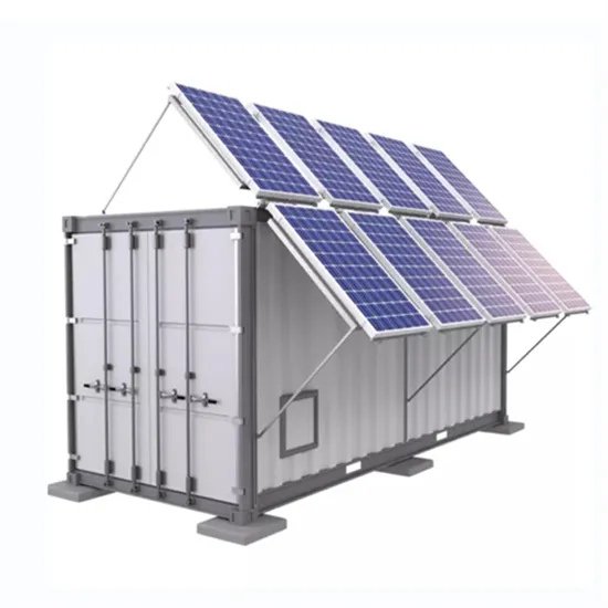
The global solar storage container market is experiencing explosive growth, with demand increasing by over 200% in the past two years. Pre-fabricated containerized solutions now account for approximately 35% of all new utility-scale storage deployments worldwide. North America leads with 40% market share, driven by streamlined permitting processes and tax incentives that reduce total project costs by 15-25%. Europe follows closely with 32% market share, where standardized container designs have cut installation timelines by 60% compared to traditional built-in-place systems. Asia-Pacific represents the fastest-growing region at 45% CAGR, with China's manufacturing scale reducing container prices by 18% annually. Emerging markets in Africa and Latin America are adopting mobile container solutions for rapid electrification, with typical payback periods of 3-5 years. Major projects now deploy clusters of 20+ containers creating storage farms with 100+MWh capacity at costs below $280/kWh.
Technological advancements are dramatically improving solar storage container performance while reducing costs. Next-generation thermal management systems maintain optimal operating temperatures with 40% less energy consumption, extending battery lifespan to 15+ years. Standardized plug-and-play designs have reduced installation costs from $80/kWh to $45/kWh since 2023. Smart integration features now allow multiple containers to operate as coordinated virtual power plants, increasing revenue potential by 25% through peak shaving and grid services. Safety innovations including multi-stage fire suppression and gas detection systems have reduced insurance premiums by 30% for container-based projects. New modular designs enable capacity expansion through simple container additions at just $210/kWh for incremental capacity. These innovations have improved ROI significantly, with commercial projects typically achieving payback in 4-7 years depending on local electricity rates and incentive programs. Recent pricing trends show 20ft containers (1-2MWh) starting at $350,000 and 40ft containers (3-6MWh) from $650,000, with volume discounts available for large orders.