Apr 14, 2022 · This article compares two strategies for seamless (re)connection of grid-forming inverters to a microgrid powered by droop-controlled inverters. While an incoming inverter
Jan 24, 2025 · 1. Introduction This communication adopts Modbus-RTU protocol, and applies to the communication between EVVO PV grid-connected string inverters and the upper computer
Sep 29, 2015 · In the context of off-grid telecommunication applications, offgrid base stations (BSs) are commonly used due to their ability to provide radio
Jan 21, 2025 · Open the web browser of your smart device and enter the IP address 169.254.12.3 in the address bar. After the access address of the product has been entered, a message
Sep 12, 2023 · 1.3 Purpose The purpose of the UNIFI Specifications for Grid-forming Inverter-based Resources is to provide uniform technical requirements for the interconnection,
5 days ago · Description - Quick user manual, delivery inspection report, packing list, warranty card, and certificate 12, used for binding the cables 4, M6 x 45, used for wall-mounting to
Jul 26, 2024 · Applying the appropriate communication technology to support grid requirements depends upon many factors beyond just the communication technology, how it is deployed
A telecommunications company in Central Asia built a communication base station in a desert region far from the power grid. Due to harsh climate conditions and the absence of on-site
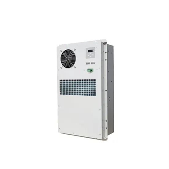
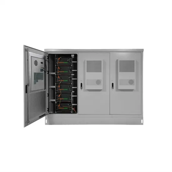
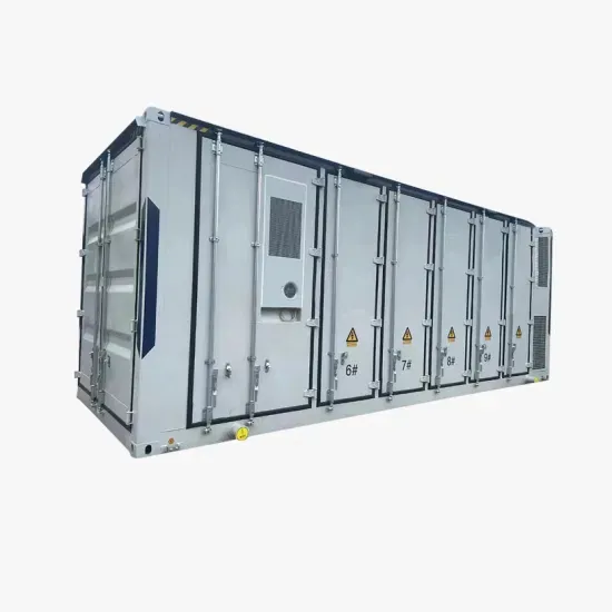
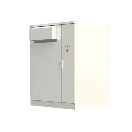
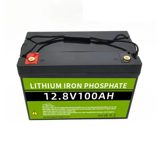
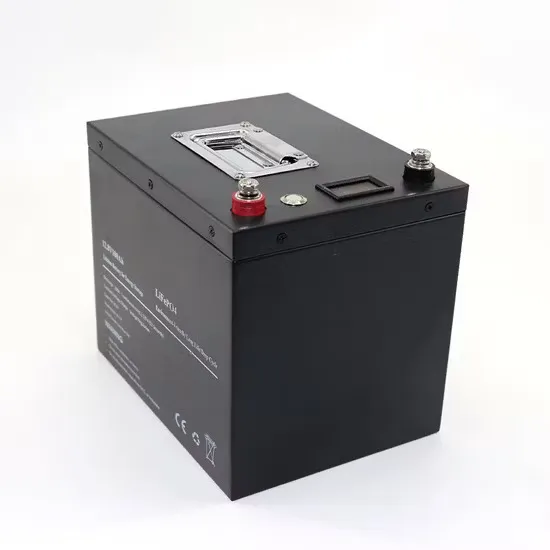
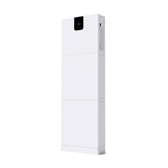
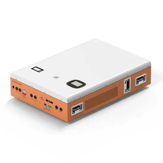
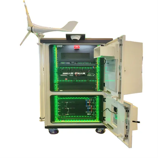
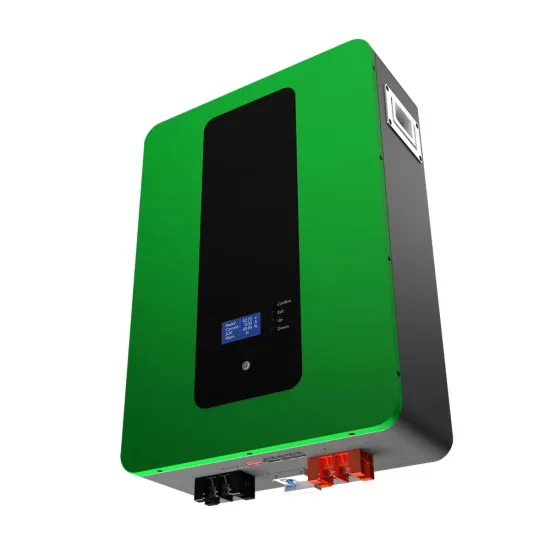
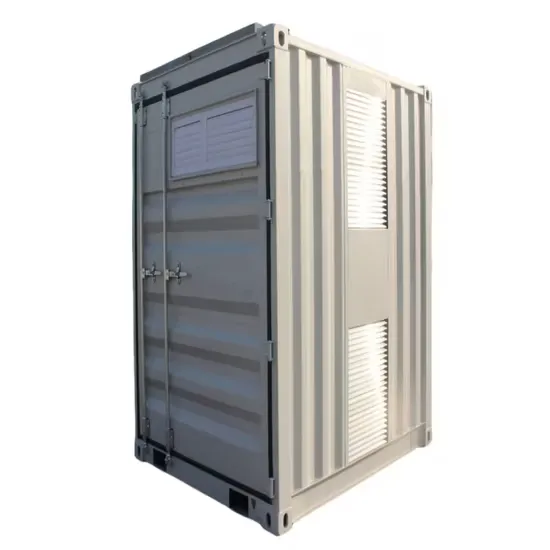
Energy storage system of communication base station Base station energy cabinet: floor-standing, used in communication base stations, smart cities, smart transportation, power
Jan 1, 2024 · With the development of modern and innovative inverter topologies, efficiency, size, weight, and reliability have all increased dramatically. This paper provides a thorough
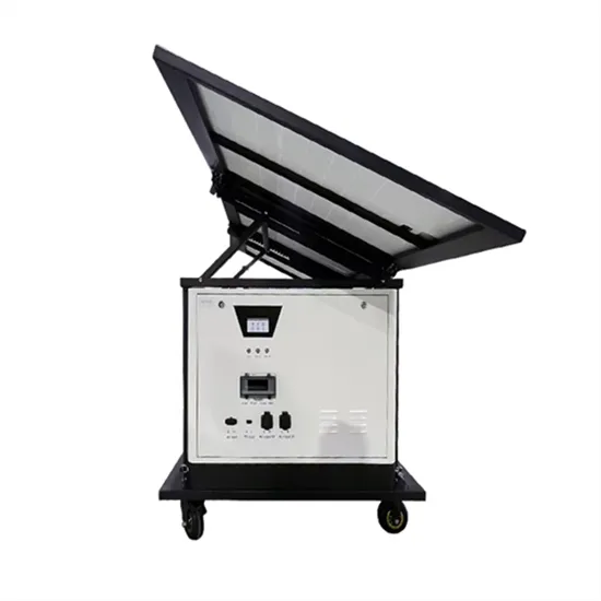
Aug 4, 2025 · The solar power for base station solution provides an economical and efficient energy solution for communication base stations, reducing operating costs, emissions, and
Oct 18, 2018 · PVS980-CS-US – 2 to 4.4 MVA The medium voltage compact skid is a cost-efficient and robust solution designed for large-scale solar power generation and to be
5 days ago · Figure 3 Parameter Menus Initial grid connection allows the inverter to be initialised by setting the country setting whereas each of the parameter settings can be used to
Nov 27, 2023 · Wireless Communication ZigBee Kit (Optional): Enables wireless connection of one or several devices to a ZigBee gateway, for wireless communication to the SolarEdge
Feb 15, 2025 · Existing grid-connected inverters encounter stability issues when facing nonlinear changes in the grid, and current solutions struggle to manage complex grid environments
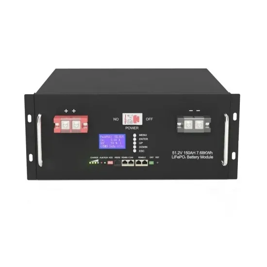
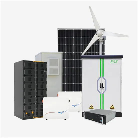
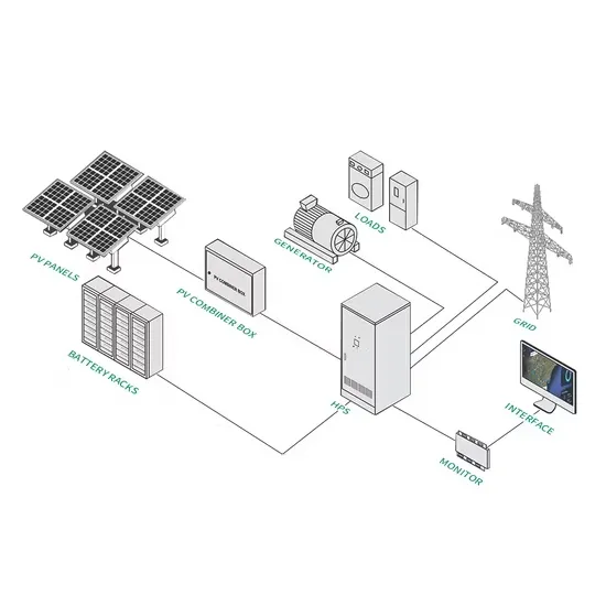
Jul 9, 2025 · The system is mainly used for the Grid-PV Hybrid solution in telecom base stations and machine rooms, as well as off-grid PV base stations, Wind-PV hybrid power base stations
Jun 17, 2024 · The following document provides a list of all US grid types SMA US model inverters are compatible with - Inverters & Utility Grid Configuration. Additional information for inverter
Aug 19, 2024 · Fault code Fault name 2, 3, 14, 15 Grid Overvoltage 4, 5 Grid Undervoltage 8 Grid Overfrequency 9 Grid Underfrequency 10 Grid Power Outage 12 Excess Leakage Current 13
Sep 3, 2024 · New US regulations for grid-tied inverters are set to take effect in January 2026, impacting manufacturers, installers, and consumers by introducing enhanced safety,
Jun 4, 2020 · 2.2 Inverter States The CPS 14 - 36kW TL inverters have 5 operational states built into the inverters as described in the table below. The inverter operational state can be read
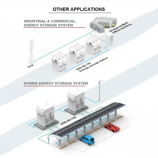
Dec 30, 2024 · Additionally, exploring the integration of communication base stations into the system''s flexibility adjustment mechanisms during the configuration is important to address the
r system operation with grid-forming (GFM) resources. In some cases, those requirements may not be appropriate for or ay even inadvertently limit the use of GFM resources. The UNiversal Interoperability for grid-Forming Inverters (UNIFI) Consortium is addressing funda-mental challenges facing the integration of GFM inverters in elec
The inverter can be programmed either by using the LCD interface or Modbus communications using registers 0x1039 - 0x1042. The Reactive Power output in Volt VAr mode can be calculated in in the following manner. Reactive Power (VAr) output = TmpQSet/1000 * Inverter Rated Power. Note that VAr is limited to 60% of the inverter nameplate power rating.
The amount of VAr can be programmed to be dependent on Grid voltage. The CPS 23 -36kW TL inverters are capable of running in 4 different reactive power modes. One of the Reactive Power modes must be selected before attempting to control any of the Reactive Power control functionality:
The CPS 23 -36kW TL inverters are capable of running in 4 different reactive power modes. One of the Reactive Power modes must be selected before attempting to control any of the Reactive Power control functionality: The inverter will not produce any reactive power in Disable Reactive Power Control Mode (0). 1. Write 0 to register 0x1047
The CPS 14 - 36kW TL inverters have 5 operational states built into the inverters as described in the table below. The inverter operational state can be read from either the front panel LEDs or by reading Modbus register 0x002F. Inverter is in Fault State and is not producing power. Site visit may be required.
The CPS 14 - 36kW TL inverters Modbus register listing may contain some registers that are not supported for all inverter models. The inverter will respond with the following values if a feature is not supported for a specific inverter model. Not Implemented for an int16 is 0x8000. Not Implemented for a uint16 is 0xFFFF.
The global solar storage container market is experiencing explosive growth, with demand increasing by over 200% in the past two years. Pre-fabricated containerized solutions now account for approximately 35% of all new utility-scale storage deployments worldwide. North America leads with 40% market share, driven by streamlined permitting processes and tax incentives that reduce total project costs by 15-25%. Europe follows closely with 32% market share, where standardized container designs have cut installation timelines by 60% compared to traditional built-in-place systems. Asia-Pacific represents the fastest-growing region at 45% CAGR, with China's manufacturing scale reducing container prices by 18% annually. Emerging markets in Africa and Latin America are adopting mobile container solutions for rapid electrification, with typical payback periods of 3-5 years. Major projects now deploy clusters of 20+ containers creating storage farms with 100+MWh capacity at costs below $280/kWh.
Technological advancements are dramatically improving solar storage container performance while reducing costs. Next-generation thermal management systems maintain optimal operating temperatures with 40% less energy consumption, extending battery lifespan to 15+ years. Standardized plug-and-play designs have reduced installation costs from $80/kWh to $45/kWh since 2023. Smart integration features now allow multiple containers to operate as coordinated virtual power plants, increasing revenue potential by 25% through peak shaving and grid services. Safety innovations including multi-stage fire suppression and gas detection systems have reduced insurance premiums by 30% for container-based projects. New modular designs enable capacity expansion through simple container additions at just $210/kWh for incremental capacity. These innovations have improved ROI significantly, with commercial projects typically achieving payback in 4-7 years depending on local electricity rates and incentive programs. Recent pricing trends show 20ft containers (1-2MWh) starting at $350,000 and 40ft containers (3-6MWh) from $650,000, with volume discounts available for large orders.