Oct 26, 2021 · The existing 7 level inverter contains 6 switches and the 9 level inverter contains only 7 switch to create the stepped ac sinusoidal output waveform. The proposed inverter has
May 18, 2020 · The conventional inverter has multiple sources and has 16 switches are required and also more number of voltage sources required. The proposed inverter required single
Jul 15, 2021 · 1. Introduction A multilevel inverter is a power electronic device which converts the lower level dc voltage into desired alternating voltage. A Multi-level inverter is used in order to
May 20, 2016 · The single phase cascaded five level inverter topology [22] has been proposed in Fig.1 .The circuit consists of eight main switches in two series connected H-bridge
Dec 12, 2020 · Two-level inverter Figure 1 indicates a single phase H bridge inverter having 4 switches. Usually, an IGBT is used as a switch in an inverter. It is observed that an R-L load is
Jun 17, 2020 · ABSTRACT - Multilevel inverter composed of an array of power semiconductor and capacitive voltage source generates multiple step voltage waveforms with variable frequency
Apr 8, 2024 · These inverters use a high switching frequency with the use of "pulse width modulation (PWM)" technology to minimize ripple and achieve a nearly sinusoidal waveform of
Mar 1, 2024 · Additionally, to minimize voltage ripple in the dc link capacitor, improve waveform quality, achieve lower capacitor voltage ripple, and ensure more uniform power distribution, a
Jan 1, 2021 · The inverter type also determines the controlled waveform at the output, whether a CSI to control current source or a VSI for controlling the voltage source. Since the VSI covers
Feb 11, 2017 · single phase 5 level Flying Capacitor Multilevel Inverter. In order to obtain multilevel output voltage waveforms, a switching trategy based on calculating switching angles
Oct 7, 2022 · As the multilevel inverter''s voltage levels increase, harmonics are reduced as well, which considerably reduces losses. This paper discusses the Level Shifted Carriers Based
Apr 20, 2020 · Currently, multilevel inverters have been increased the number of applications in the industrial sector and renewable energy sources. Among its
Jul 27, 2016 · A five-level output phase voltage waveform can be obtained with two separate dc sources and two H-bridge cells. Each inverter level can generate three different voltage
Jan 24, 2024 · A hybrid MLI structure for three three-phase supply is realized using three-phase 2-level and two numbers of single-phase H-Bridge inverters 12, 13, 14. The topology uses a
Jan 2, 2018 · Abstract - This paper presents a switch three level and five level diode clamped multilevel inverter topology which can be used for low-medium power drive applications. The
2 days ago · A single-phase Cascaded H-bridge Multilevel Inverter with Voltage Boost Ability: Modulation and Analysis (IEEE Transactions on Industry Applications, 2024). Pourfarrokh, S.,
Jul 19, 2022 · Multi-level inverter techniques are used in industrial applications to reduce voltage stress on power equipment and create high-quality output voltages. Multi-level inverters
Oct 9, 2022 · The voltage source inverters generate an output voltage or a current with levels either 0 or +Vdc or –Vdc. They are recognized as the two-level inverter. To gain a quality
Jan 1, 2020 · The comparison of single phase three-level, five-level and seven-level flying capacitor multilevel inverters is carried out with respect to
Apr 27, 2024 · ABSTRACT: This paper presents a single-phase multi-string multilevel inverter for micro grid applications. The multilevel topology consists of few H-bridges connected in series,
A single-phase cascaded multilevel inverter based on a new basic unit with reduced number of power switches. IEEE Trans. Ind. Electron. pp. 922-929. R. Majdoul, A. Touati, A. Aitelmahjoub, M. Zegrari, A. Taouni, A. Ouchatti. 2020. A Nine-Switch Nine-Level Voltage Inverter New Topology with Optimal Modulation Technique.
A single-phase transformerless PV inverter topology can be categorized based on several factors. These include the number of input dc-link voltage (single, double, etc.) and the fundamental origin of topology (H-bridge, NPC, etc.) .
Generally, multilevel inverters are classified into three categories: Neutral-point-clamped (NPC) inverters (see Figure-1), Flying capacitor (FC) inverters (see Figure-2), and Multi-cell multilevel (ML) inverters (see Figure-3). Neutral-point-clamped (NPC) inverters are the most widely used multilevel inverter topology in high power applications.
This paper proposes one such improved single phase inverter topology. The proposed structure is corroborated by formulating a nine-level inverter. Further, the proposed structure is compared with the traditional asymmetric structure in terms of LSR.
Many new inverter structures have been developed and modified to improve the level to switch ratio (LSR). This paper proposes one such improved single phase inverter topology. The proposed structure is corroborated by formulating a nine-level inverter.
A single-phase 11-level HT-type multilevel inverter. ogy in , but using three modules. T-type modules are located at each end of the topol- ogy, d enoted as T and T’. Switching devices, St and St ’ where (i = 15), are u tilized in these modules. Other modules, or switching devices, are positioned between the T-type
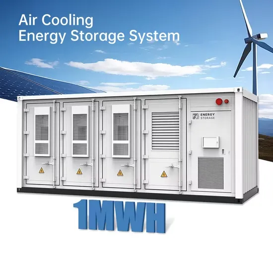
The global solar storage container market is experiencing explosive growth, with demand increasing by over 200% in the past two years. Pre-fabricated containerized solutions now account for approximately 35% of all new utility-scale storage deployments worldwide. North America leads with 40% market share, driven by streamlined permitting processes and tax incentives that reduce total project costs by 15-25%. Europe follows closely with 32% market share, where standardized container designs have cut installation timelines by 60% compared to traditional built-in-place systems. Asia-Pacific represents the fastest-growing region at 45% CAGR, with China's manufacturing scale reducing container prices by 18% annually. Emerging markets in Africa and Latin America are adopting mobile container solutions for rapid electrification, with typical payback periods of 3-5 years. Major projects now deploy clusters of 20+ containers creating storage farms with 100+MWh capacity at costs below $280/kWh.
Technological advancements are dramatically improving solar storage container performance while reducing costs. Next-generation thermal management systems maintain optimal operating temperatures with 40% less energy consumption, extending battery lifespan to 15+ years. Standardized plug-and-play designs have reduced installation costs from $80/kWh to $45/kWh since 2023. Smart integration features now allow multiple containers to operate as coordinated virtual power plants, increasing revenue potential by 25% through peak shaving and grid services. Safety innovations including multi-stage fire suppression and gas detection systems have reduced insurance premiums by 30% for container-based projects. New modular designs enable capacity expansion through simple container additions at just $210/kWh for incremental capacity. These innovations have improved ROI significantly, with commercial projects typically achieving payback in 4-7 years depending on local electricity rates and incentive programs. Recent pricing trends show 20ft containers (1-2MWh) starting at $350,000 and 40ft containers (3-6MWh) from $650,000, with volume discounts available for large orders.